This issue’s questions come from an Engineer and a Masonry Inspector. What questions do you have? Send them to info@masonrymagazine.com, attention: Technical Talk.
For reinforced masonry, “typical” running bond has ½ unit overlap so that the cells of 2 cell units align sufficiently to install grout and reinforcement (See Figure 1). Stack bond is typically where there is no unit overlap (Figure 2). The cells will also align for grouting. Stack bond is a specific condition of masonry laid in “other than running bond.” Figure 1 says stack bond, but it should be “other than running bond”.
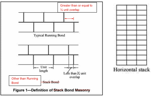 Figures 1 and 2 courtesy of CMHA (TEK 14-06) and modified
Now, how do these two bond patterns relate to your question of effective compressive width?
TMS 402-22 provides the answer in Section 5.1.2 and the following Figure CC-5.1-2 from the Commentary. “b” is the effective compressive width you asked about. There are two methods to determine “b”.
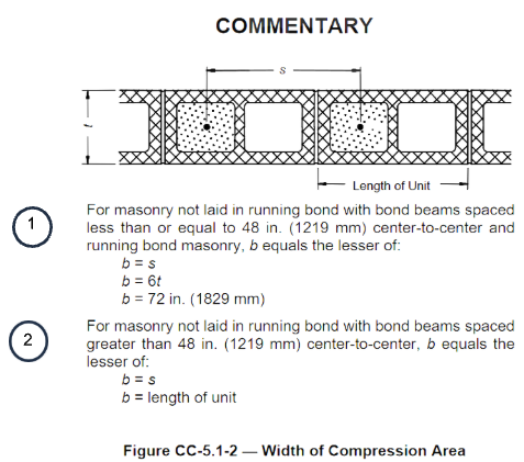
Courtesy of The Masonry SocietyMethod 1 for determining b for masonry laid in running bond limits b to the lesser of the 6t criteria, the bar spacing, and 72 inches. This same criteria applies to masonry laid in “other than running bond,” provided the wall has horizontal bond beams spaced less than or equal to 48 inches on center.
Method 2 for determining b for masonry laid in “other than running bond” (not laid in running bond) limits b to the lesser of the bar spacing or the length of the unit. No bond beams are required. If bond beams are included in the design, they will not affect this method if their spacing exceeds 48 inches.
So, for masonry laid in “other than running bond,” which method is preferred for selecting the effective compressive width?
- Method 1 would likely provide a more efficient design, and therefore more economical, when bond beams at 48 inches or less on center are required for other reasons, such as in-plane shear, since the 6t criteria would always exceed the unit length. For example, if Special Reinforced Shear Walls are required, the bond beam spacing must be 24 inches on center or less. Therefore, Method 1 is the method to use to determine ”b” because there is no added cost for meeting the bond beam spacing requirement.
- Method 2 would likely be more economical if:
- The design bar spacing is less than the length of the units being used, and no bond beams would be required, or
- Additional bond beams would be needed to achieve Method 1.
Summary:
- The major factor affecting the choice of the effective compressive width is whether bond beams at 48 inches on center or less are required, no matter which method is used to determine “b”.
- Adding bond beams just to enlarge the effective compressive width is generally not cost-effective. When in doubt, run the calculations both ways and let economy guide your decision.
Q. A Masonry Inspector asks whether it is acceptable per TMS 602, Specifications for Masonry Structures for masons to rest horizontal bars on the cut webs of knockout bond beams. Some masons say they regularly use the cross webs to support the bars. Her interpretation is that supporting the bars on the webs does not provide the required grout cover with the masonry at these webs. To support her interpretation, she cites the IMI detail for knockouts. This figure shows the horizontal bars elevated above the webs and fully surrounded by grout.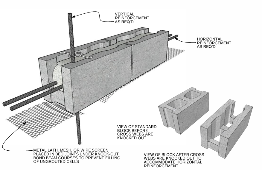 Knock-out Bond Beams for CMU
Diagram 02.410.0141 available in SketchUp 3D Warehouse (courtesy of IMI)
A. This is an interesting question. Knockout units have been used for decades. TMS 602 does not specifically prohibit supporting horizontal bars on the webs of knockout bond beams. In fact, it specifically allows the practice in Article 3.4B.3, which states, “Maintain clear distance between reinforcing bars or mechanical splices and the interior of masonry unit or formed surface of at least ¼ in. (6.4 mm) for fine grout and ½ in. for coarse grout, except where cross webs of hollow units are used as supports for horizontal reinforcement.” The underline is for emphasis. This specifically allows cross webs to support horizontal bars, provided the other interior clearances are maintained.Under what circumstances would supporting bars on the cross webs not be acceptable?
Using the IMI detail and modifying it so the bars are supported by the cross webs, we see:
- The 2 bars (shown dark) with adjacent splice bars. These must be able to clear the vertical bar in the center. This becomes more difficult when double offset vertical bars are used.
- For grout clearance, the bars must be clear of the interior face shells (1/4 in. for fine grout, and ½ in. for coarse grout).
- The design cover (x) must be provided to match the contract documents to achieve the design d distance.
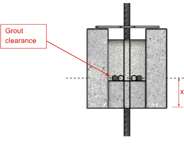 Figure 3 - Modified IMI detail where bars are supported by cross webs.
If we have satisfied all three of these criteria, is the design adequate? Not necessarily! The concern is that grout may not flow around the bars well enough to fully encase them.
TMS considers this possibility in Table 7 of TMS 602, which provides requirements for Grout Spaces, specifically the column titled “Minimum clear width of grout space”.
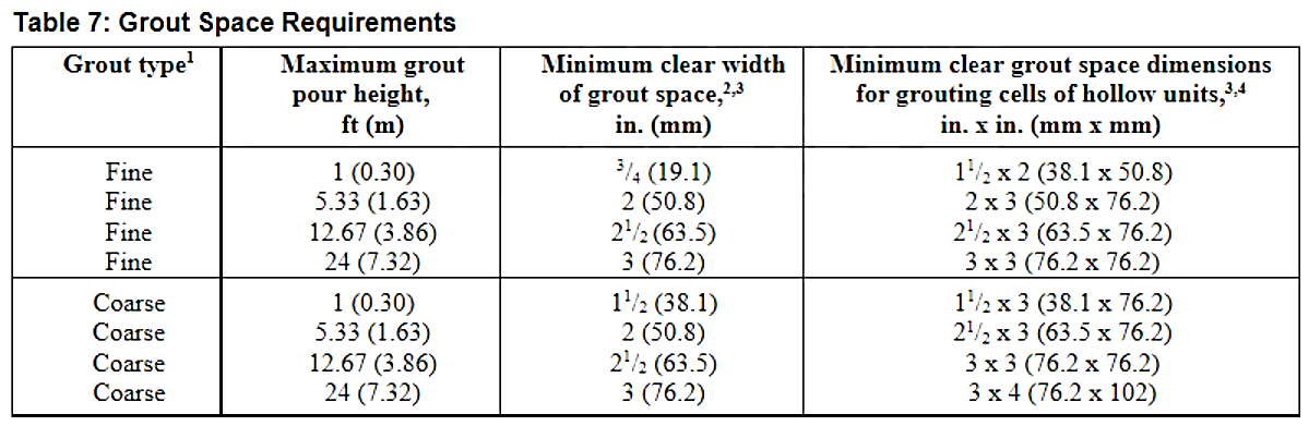 TMS 602, Table 7 - Courtesy of The Masonry Society
Footnote 3 defines the Grout space as:

In Figure 3, the only grout space available is the grout clearance and the thickness of the vertical bar. From Table 1, this could likely reduce the maximum pour height to 1 foot or more. To compensate and provide more grout space, the splices could be stacked (Figure 4), but the grout cover (x) will increase and affect the design d distance. This is more likely for designs where bond beams are used for the masonry beams.
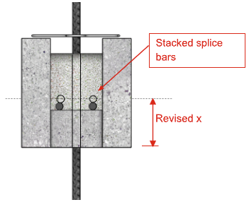 Figure 4 - Modified IMI detail where bars are supported by cross webs.Summary:
- It is acceptable per TMS 602 to support horizontal bars on the webs of knock-out bond beams provided all the other clearance criteria are met, and the selected grout pour height meets Table 7 for the design grout space.
- Everything discussed for horizontal bars supported by cross webs also applies to suspended reinforcement given in the IMI detail (Diagram 02.410.0141).
- The IMI might make detection of grout voids under the horizontal bars easier. One recommendation would be for designers to require a demonstration panel for the grouting of knockout bond beams to ensure the grout can be installed and consolidated/reconsolidated adequately.
Thank you again for following this column. Remember, by bonding, we get stronger! Keep the questions coming. Send them and your comments to info@masonrymagazine.com, with attention to Technical Talk. If you have missed any of the previous articles, you can find them online for Technical Talk, Bonding with Masonry at Masonry Design magazine.
___
David is a PE, SE with Biggs Consulting Engineering, Saratoga Springs, NY, USA (www.biggsconsulting.net). He specializes in masonry design, historic preservation, forensic evaluations, and masonry product development.
Keywords for this issue: other than running bond, stack bond, effective compressive width, knock-out bond beams, grouting